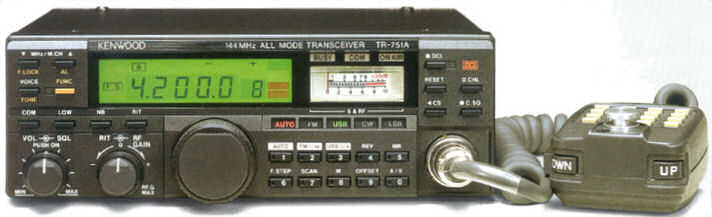
Actually a photo of the TR751A but looks identical to TR751E
The Kenwood TR-751E is an ageing but still fantastic 2m (144MHz) multimode transceiver. Like all things, me included, as they get older parts start to fail. The TR-751E I had to repair had been dropped, which meant the RF Gain / RIT dual concentric potentiometer needed straightening…the main VFO knob had already been glued. It also had a dry joint, which was repaired and an adjacent capacitor replaced, just in case.
It was reported that it was ‘warbling’ on SSB but OK on FM, and the ‘S’ meter was misbehaving. When I checked it, after about 60 seconds, the receiver noise was pulsing about every two seconds, with a corresponding deflection of the meter. Transmit power output seemed to be similarly affected.
The troublesome beast
On checking the radio, it was found that the -6v rail, which is derived from a little inverter board, was dropping out in sympathy. Freezer spray suggested the two 33uF electrolytics could be the cause, but sadly the fault remained when these were replaced. There is a little daughter board, Kenwood part number X59-1100-00, which is driven from 12v on the TR-751E and generates a -6v supply. These are no longer available so an alternative was sought.
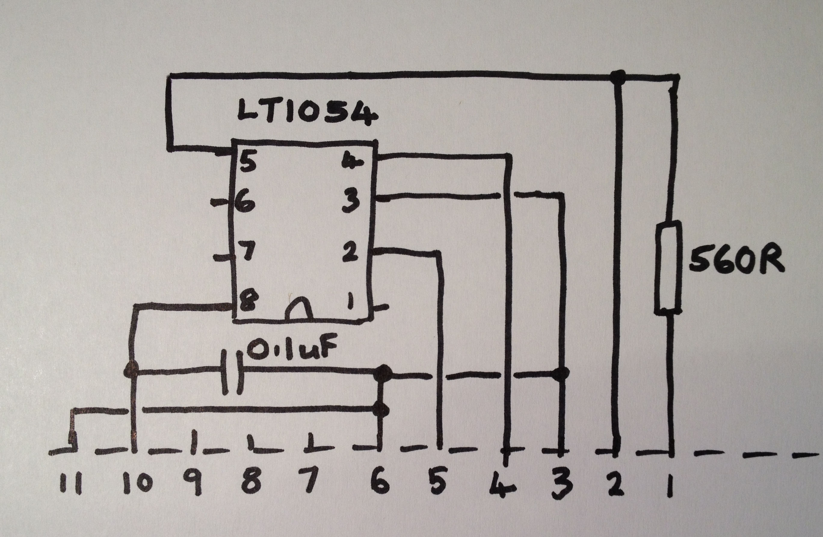
Schematic of new -6v inverter
The little 8 pin LT1054 chip is designed to do exactly what Kenwood’s board does so I made up a module using one of those…making a PCB was a bit ambitious in this case, so I used a small piece of veroboard. Some pictures of the board are below…it fits exactly where the old board was installed and you don’t need to change anything on the main circuit board.
Above is the schematic / circuit diagram of the new -6v inverter board, laid out as it will be made on veroboard. Note: the picture doesn’t show pin 9 being grounded, which it is on the pictures of the actual board.
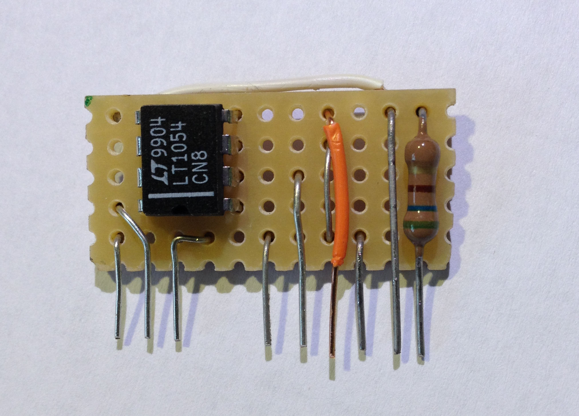
New -6v inverter on veroboard – front
This is the front of the board – note the insulated wire on one connection and the placement of the links.
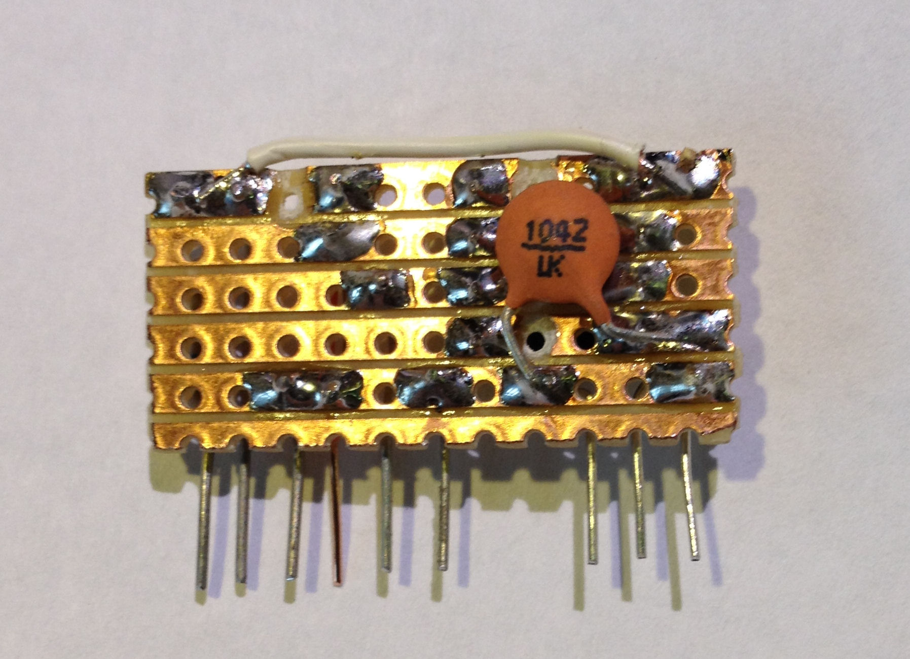
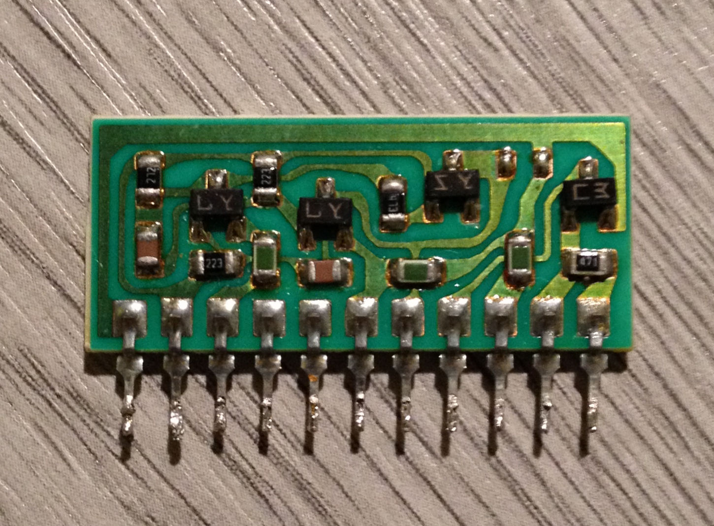
New -6v inverter on veroboard – back
Here we have the rear of the board. All four tracks between the LT1054 pins are cut using the special Vero tool or a small drill. There is one further track cut at the top left, and an insulated bridging wire. It would have been nice not to need the bridging wire, but the board was meant to be the same size as the original. The left hand wire on the ceramic capacitor is only connected to the common ground rail at the bottom, it is raised above the LT1054 pins to avoid a short.
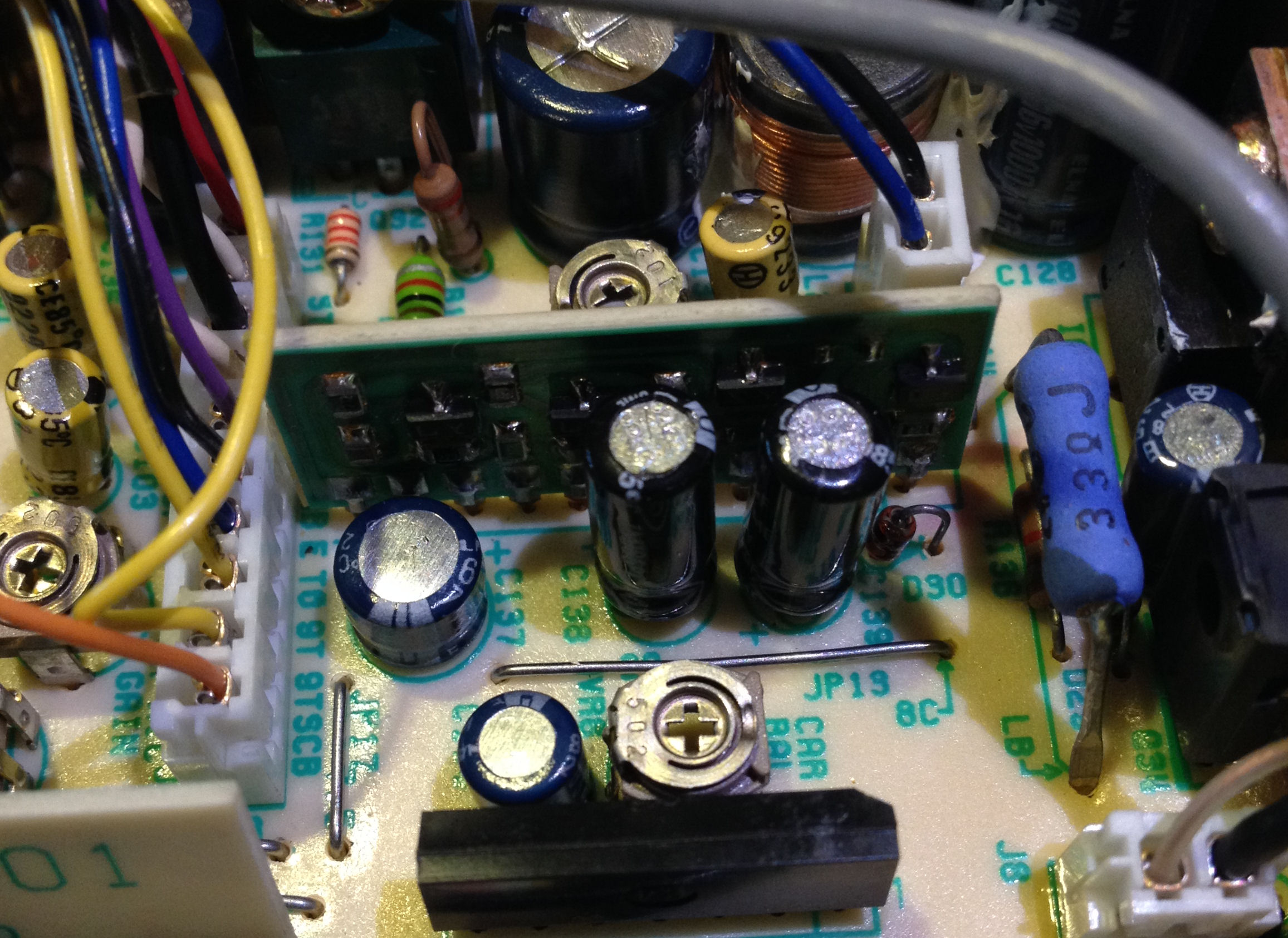
Kenwood X59-1100-00 in situ
This is the original Kenwood X59-1100-00 in situ…it looks innocent but is guilty as hell. The two black capacitors in front of the board are the 33uF 25v ones used in the inverter. It may pay you to change those too…while you have the radio apart.
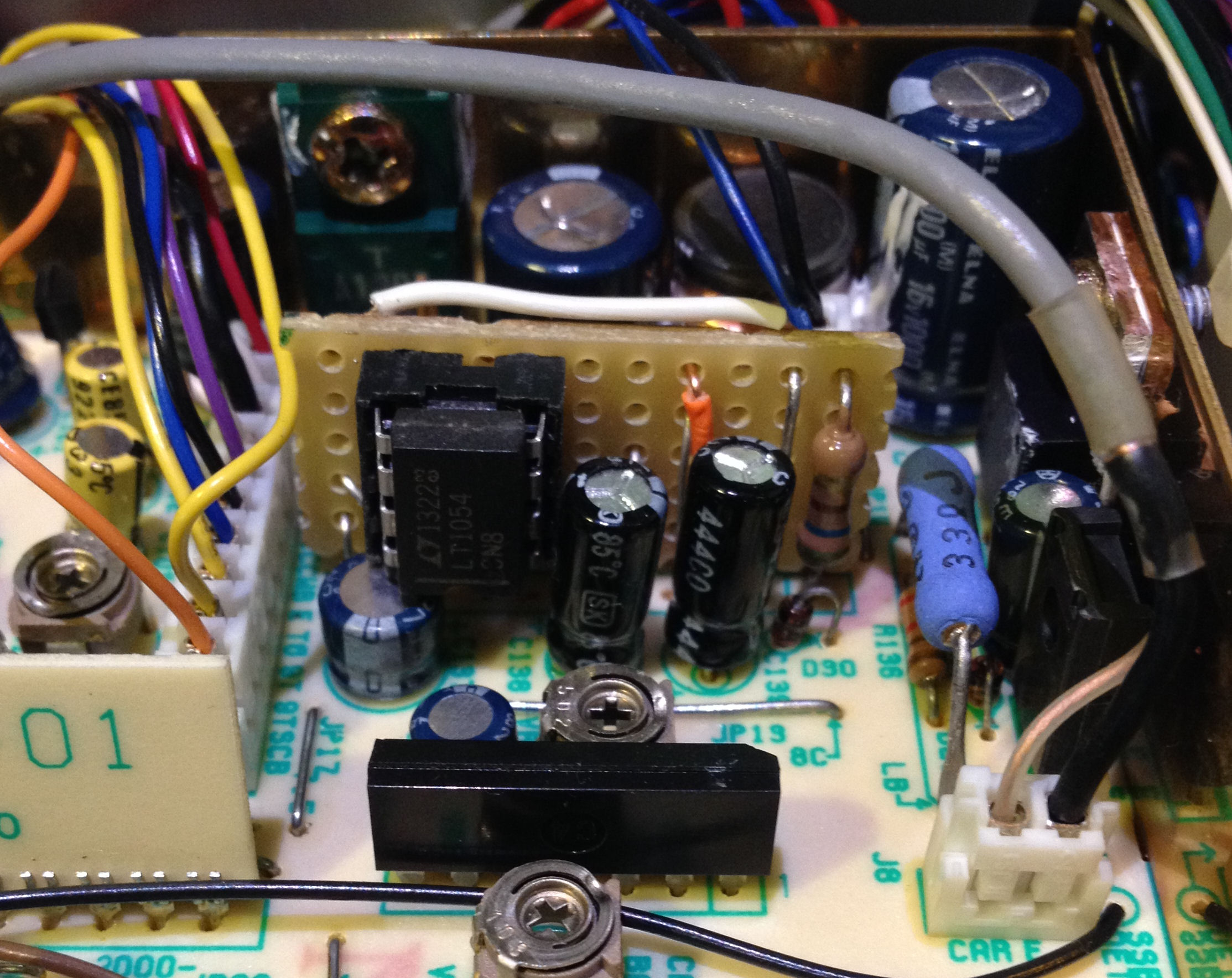
Replacement -6v Inverter
Here is the finished board, installed in the Kenwood TR-751E. The first LT1054 I soldered in was dead (no…I didn’t overheat it) so I put a socket in and the second chip worked. By the way, the third one I had was dead too when tested in the socketed board. Note that it is a snug fit next to the other components…but if the chip ever fails, it can be swapped in a few minutes.
The new -6v inverter board now fitted to the Kenwood TR-751E should now last the life of the radio, so if you have the same problem, you know how to fix it. Since writing this article, I’ve discovered that others have come to a similar conclusion, and their boards are almost identical. Problems with the -6v inverter seem to be fairly common, often the first indication of trouble is when the ‘S’ meter shoots over to the right hand stop for no reason.