If you are the proud owner of a Kenwood TS790E, you may be rather miffed that it won’t work with modern repeaters requiring CTCSS tones; the TS790E was made in the days of 1750Hz toneburst for repeater access in the UK.
Kenwood TS790 – the ‘A’ version
Both Kenwood and their dealers will probably tell you there’s nothing that can be done…don’t buy the optional tone board, as it’s used for incoming CTCSS only and there’s no socket on the TS790E to install it anyway.
There is a solution, which requires a bit of surgery to your radio…and you perform the surgery entirely at your own risk. Here we go:
Preparation
This may seem obvious, but ensure the power is disconnected…it might be prudent to disconnect the aerial(s) and microphone etc… too. Make sure you have plenty of room to work and that you take the requisite anti-static precautions.
Dismantling and Modifications
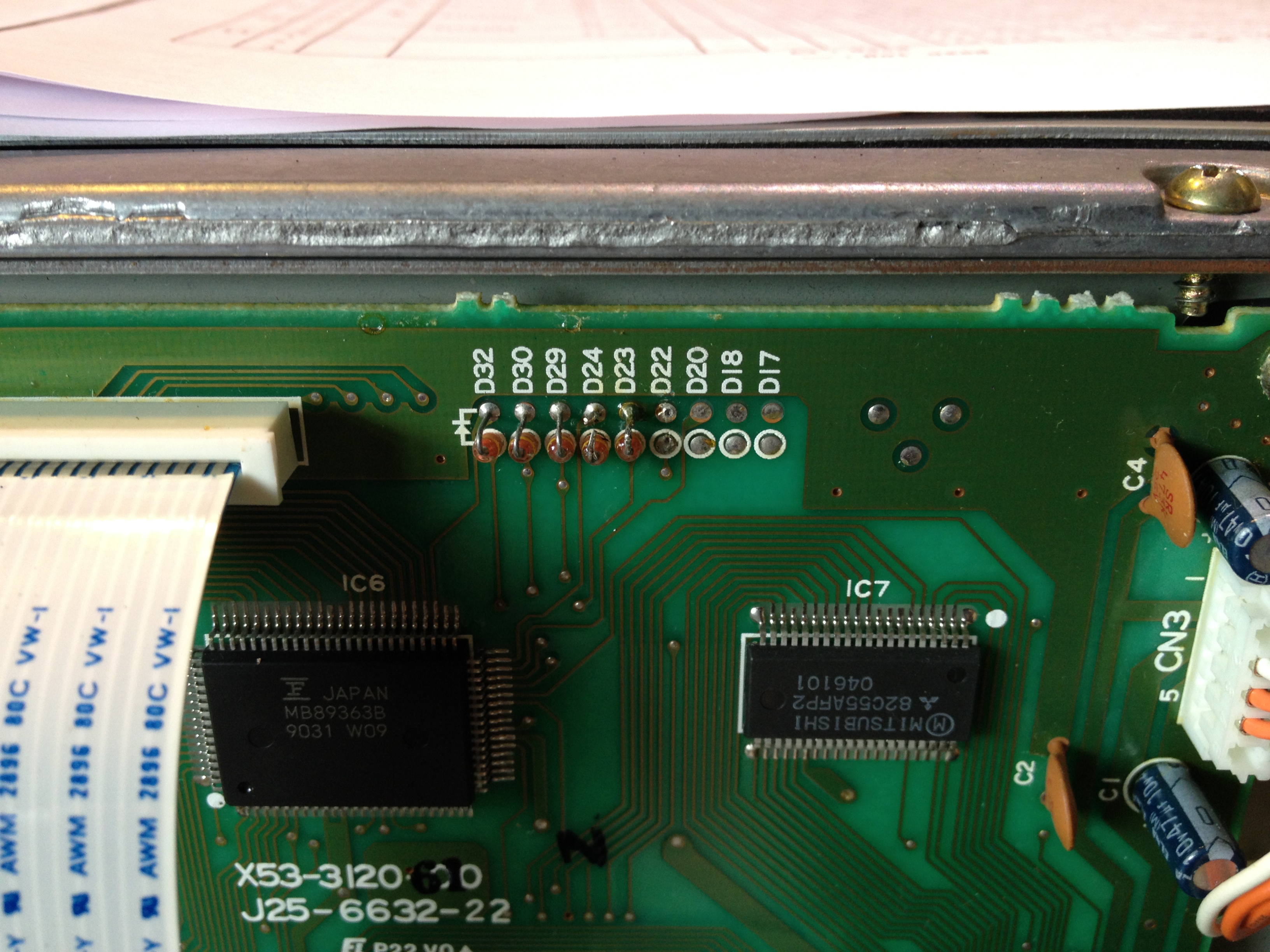
TS790 Control Board showing diodes
Carefully remove the top and bottom covers from your TS790E, making sure you don’t damage any cables or poke your fingers through the speaker cone. Sit the radio on your bench with the front towards you and just overhanging the edge of the bench…oh, and it needs to be the right way up.
- There are four screws, two on each side, of the front panel assembly that secure the panel to the rest of the radio. Loosen the bottom two and remove the top two whilst supporting the front panel. It should now hinge down exposing the control board.
- On the left hand side of the control board is a metal clip holding an IC on a heatsink…carefully remove the clip. Then, remove the screws securing the control board to the metal chassis of the radio. Be careful you don’t damage any cables…you don’t need to unplug anything luckily.
-
TS790 Diodes
You should see a line of diodes, right of centre on the control board. They are labelled D32 to D17. But Kenwood are sneaky and there’s a diode on the back of the board (D21) which is why you’ve removed it.
- You now need to cut some diodes…I can’t think why, but just in case you want to reinstate the radio, cut the middle of the exposed leads and move the cut wire away from the diode a little. Cut D23 and D24 only.
- On the reverse of the board is the surface mount D21. You can remove it, but I suggest you carefully cut the track to the right of the cathode end of the diode.
- Next, you need to install a diode in position D22 in the line-up. Carefully clear the solder blocked holes using a solder sucker and install a 1N4148 or similar…note the correct orientation on the diagram above. Solder it in carefully, trim the leads and check your work.
- Now you need to reassemble the radio…which, although it may surprise you, is simply the reverse of the dismantling process. Do remember to put the metal clip back on the IC and heatsink, and to secure the black single wire under the top left control board screw. Don’t put the covers on just yet…Murphy’s law and all that 😉
- If you’re happy that all is well, connect up the various cables and power supply. I suggest you hold the ‘A=B’ button whilst pressing ‘Power On’ so that the CPU is reset.

Finishing Off
Assuming all is well, you should be able to ‘SELect’ the CTCSS tone and turn it on and off…check your manual for the ‘how to’. You will need to go in and set the channel frequency step to 12.5KHz and the 430MHz repeater offset default to 1.6MHz.

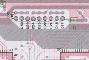
TS790 Diode Matrix
It’s now time to replace the top and bottom covers and retire for a cup of tea. Congratulate yourself that you have become the proud owner of a TS790A. What you have in fact done, is change the TS790E (European) into a TS790A(American). You can also access the new extended 2m allocation as a bonus. On the right is the diode matrix from the Kenwood TS790A/E service manual…for your reference.